A E T H E S I S
Lauren Paese
Dr. John Messner
Bay Area Children's Hospital
Bay Area, CA
BUILDING STATISTICS
BUILDING NAME
LOCATION
OWNER
OCCUPANCY
SIZE
NUMBER OF STORIES ABOVE GRADE
DATES OF CONSTRUCTION
OVERALL PROJECT COST
PROJECT DELIVERY METHOD
BAY AREA CHILDREN'S HOSPITAL
BAY AREA, CA
N/A
MEDICAL
521,000 SF
5
August 2011- December 2017
CANNOT BE DISCLOSED
CM AT RISK
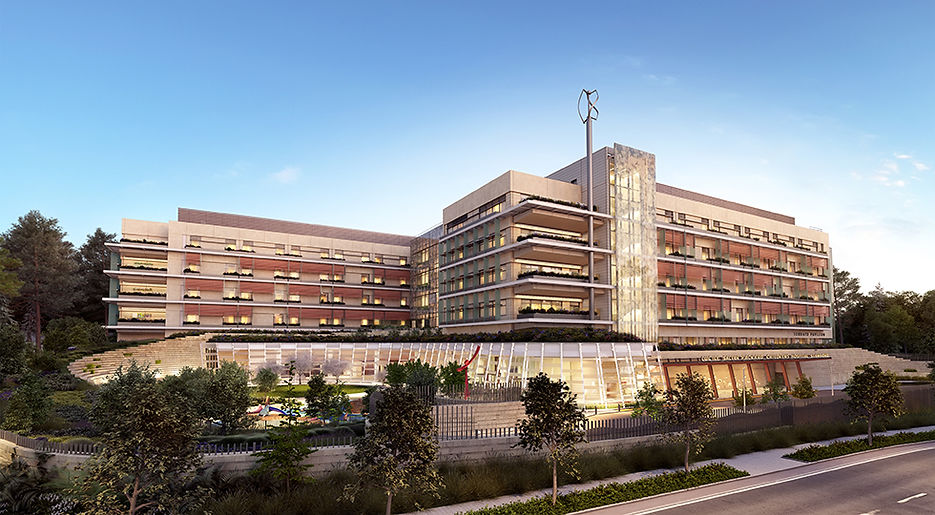
The Bay Area Children’s Hospital is an expansion off the current children’s hospital. It will add 149 patient rooms to the hospital and also include offices and family spaces. Additionally, there is a two floor parking garage underneath the facility. Recently, the Bay Area has had an increased demand for patient beds, that an expansion was necessary to meet the growing needs of the community. Through innovative sustainability features and state of the art mechanical systems, this hospital is unique and will save many lives to come.
THE TEAM


ARCHITECTURE
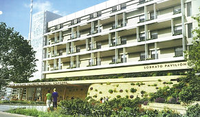
The expansion’s design mimics the current hospital’s façade with the same concrete walls and red overhangs. Also matching the nearby community, the design flows well around the area and campus. The expansion includes a large curtain wall, running in the spine from the ground floor to the 5th floor. It showcases a leaf pattern and reflects the overall design of the hospital as a tree. There are over 3.5 of garden space around and on the building creating a whimsical vibe for the children. The landscape fits in with the suburban area well.
The hospital is broken up into 3 main zones; the two towers connect by the spine. One tower holds the ICU, while the other holds regular patient beds. The spine includes the elevator, family and office spaces for most of the building. The second, third and fourth floor follow this pattern while ground and first floor hold various specialty spaces including surgical rooms, the cafeteria and the gift shop.
Applicable Codes
-
Building- 2012 IBC
-
Seismic- SEAOC
-
Gas- AGA
-
Mechanical – CMC, Title 24
-
Plumbing – CPC
-
Electrical – Title 24
-
Fire- 2012 IBC
Zoning
In the town, the building lies in the “Historical District” zone along with the original hospital. Various land uses are allowed including “churches and religious institutions”, “medical offices”, “parking facilities”, and “ambulance services” all of which are including in the Bay Are Children’s Hospital. It is also noted that for new construction over 50,000 SF and up, 4 employee showers are required.
Historical Requirements were not necessary for this building
BUILDING ENCLOSURE

GFRC Precast Wall panels with a laminated glass curtain wall. The curtain wall portrays a leaf design and has aluminum exterior sunshades at each patient room. Thermal insulation was sustained through a vapor barrier in the wall section. Glass doors and windows were custom designed to ensure maximum comfort indoors while still maintaining the architectural design goal.
For the roofing, 2 layers of EPDM were used because of its high durability. All the
heavy mechanical equipment is placed upon the roof and routine maintenance is completed. A double drain system was installed every 10’ on the roof as well. LED step lights align the edges of the roof as well. Solar shading is over each patient roof balcony creating a personal space for the children as well as limiting natural sunlight.
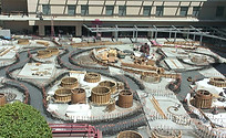
Over part the ground floor, a garden space covers the roof. A foam backfill was utilized because of its lightweight and easily adjust fit. A vapor barrier was laid on top, then soil and the grass and landscaping. The landscapes will be irrigated with rainwater and condensate water from underground cisterns.
SUSTAINABILITY


The building is targeting a LEED gold certification. With 3.5 acres of healing gardens and green space on each balcony, Children are happier and healthier- and so is the environment. The plants in the gardens are drought tolerant and are plated with mulch to retain moisture. There is also a no mow turf with an irrigation system. The spaces will save 800,000 gallons by collecting it for irrigation. The building features a wind turbine on the roof and solar panels in the garden spaces. One effort that was seen throughout the construction process was recycling over 90% of the waste in the trailers and on site.
An innovative HVAC design was utilized to reduce waste air into large spaces. In the atrium, instead of cooling and heating from the ceiling, the columns provide airflow to the functional space. This ensures unoccupied spaces are not being heated or cooled and energy is not wasted. The environment was maintained as a priority throughout the construction process.
BUILDING SYSTEMS
Construction | To construct a build of this size, great planning had to be put in place prior to actual construction. All major trades had trailers onsite next to the general contractor, engineers and architects. With everyone in close proximity to each other, all questions could be easily and quickly answered. Any discrepancies could be discussed in person. Pull planning meetings occurred once a week for various trades to ensure everyone was on the same page before anything was put into place. These meetings happened on site in the large conference room with the walls transformed into a giant calendar. Visualizing the work ahead helped many trades understand the sequence. Once construction began, weekly meetings amongst trades continued.
Electrical | The electrical system draws power from the local utilities. It then feeds into the basement electrical room and the many transformers, dropping the power to 480V or 280/ 120V in some cases. Two massive generators are located off site for emergency distribution. They are able to power the entire hospital at 100% capacity for over 60 hours in the event of a crisis. For data, servers located in 4 zones on each floor. All connect to the data center on roof. An uninterrupted Power Supply runs off a flywheel, not a battery, saving space and requiring less monitoring and management.
Mechanical | For the mechanical systems, 16 basement air handling units (AHU) and 4 rooftop AHUs supply air to all the rooms. Local Variable Air Volume (VAV) terminals are located in each zone to allow for patient and staff comfort.
Fire Protection | There are three different types of sprinkler systems throughout the building. A Pre-action system is located in the data center on the roof and some of the electrical rooms to prevent loss of confidential information or any disruptions to the essential equipment. A delayed dry systems runs throughout the rest of the electrical and mechanical rooms because it requires two signals to go off in case of a false alarm. Finally, all office rooms and patient rooms have a wet system. Most sprinkler heads are concealed pendants run overhead in the ceiling to match the aesthetics of the building.
Transportation | There are six elevators throughout the building. Four are located in the center of the footprint for daily patient and visitor use. The two additional lifts are go to the roof and are used primarily for faculty and staff. Six stairs also run throughout the building, but only two run from parking level to the roof. All stairs are steel with stained, brushed concrete finish.
Lighting | The lighting of the building was designed to keep the patients and staff feeling comfortable in content at all times. The ground floor rooms such as the cafeteria, hallways and elevator lobbies have fun round 4’ diameter LEDs that are programed to change colors. The hallways on the upper floors have warm, cove lighting running along the side. The West side of the lobby has a large, curved, curtain wall bringing in lots of natural light. Each patient room and office room has a large window to allow for daylight and views to the outdoor gardens.

Structural | Located in California, earthquakes are highly likely. Expansion joints are located within every bay and every stair landing has a 4”-12” plate. A K-braced frame allows the structure to move with any shakes. The link may move so the columns and walls do not. This also allows for quick repairs if there is are any damages.

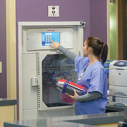
Special Systems | A pneumatic system for the hospital allows for nurses and staff to transport medicine, documents and specimens throughout the original hospital and the expansion. Eventually, the system will also connect to the planned adult hospital nearby. Each floor in the two towers has a station near the nurse stations that permit facility to send canisters up to 17 MPH. Some benefits include reducing turnaround time and improving safety by reducing errors. The control center is located in the basement in the pneumatic tube room. For the hospital, the normal system was not adequate and the owner opted for the express system, allowing more zones and more transactions per day. The old system could only support one blower per zone. Now over 10,000 can occur per day. There is 1200-1600 CFM running through the 6” steel pipes. To ensure the canisters can flow through the piping, a 48” radius is required for 90⁰ arcs. The piping material being steel is very important for safety so bleach can be used to clean the interior if there is ever a leak or accident. The 6” Eco-Seal Carriers latch closed and prevent spills while the wear bands scrub the inside of the steel tubes.